- #Altium designer protel 99se how to#
- #Altium designer protel 99se software#
- #Altium designer protel 99se professional#
- #Altium designer protel 99se download#
With the same data format used throughout the entire design, going in and out of the different tools is simple and straightforward without the need for complicated interfaces and translators. Altium Designer also features a unified design environment providing commonality between its tools. Now structured on a 64-bit multithreading system’s architecture, Altium Designer is ready to put its power to work for you. To give you the power that you need as a PCB designer for today’s challenging designs, Altium Designer has been rebuilt from the ground up. Today that PCB file experience has culminated in the best PCB design tools available on the market today, Altium Designer. Starting with Protel, Altium has over 30 years of experience in creating cutting-edge design software. As Altium Designer it carries on that advanced legacy by continually pioneering new and innovative tools that specialize in all aspects of the PCB design process. As Protel, it made history as one of the first PCB design tools created for the personal computer.
#Altium designer protel 99se download#
The answer is that the Protel PCB download is still right here and better than ever, although it is now known as Altium Designer 365. The question that often comes up though is whatever happened to Protel? Since the mid-1980s, Protel has been used for PCB design in companies all over the world as well as in universities for teaching circuit design and in homes for the hobbyist.
#Altium designer protel 99se software#
You don’t have to look very hard to find software such as Protel PCB design software or Diptrace still in use.
#Altium designer protel 99se professional#
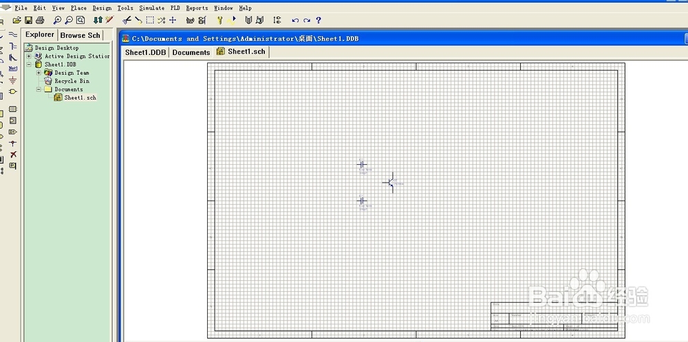
As seen in the picture below.The most powerful, modern, and easy-to-use PCB design tool for professional use. The title sequence is that we will create DESIGNING AND MAKING EQUIPMENT DRYER Phaleria MICROCONTROLLER AT89C51. Next we will start by creating a schematic diagram that we will create the documents that we created earlier, here we will use some of the components such as capacitor, Resistors, Transistors, Doide, IC, etc. įor the next option on the tool serves as a Document Manager, Document Open, Save, Print Setup, Zoom, Zoom Sch, Down Hierarchy, Cross probe, Selected Object, Object Deselect, Move, Drawing, Wiring, Run Dialog, Run Simulation, Remove Library, Place Part and Component Part Number increamentįor toolbar some of which serve as a standard tool that really should exist in any software, but there are some functions of the toolbar that is used by Protel to support such software, including Place, Design, Tool, Simulate, PLD, and Report. Erc, Graphic Image, PCB Layout Directive, and Array Placement. To the left of the tool option that serves as a wire, line, bus, Polygon, Bus Entry, Eliptical Arc, Net Label, Bezier, Power Port, Annotation, Part, Text Frame, Sheet Symbol, Rectangle, Sheet Entry, Round Rectangle, Port, elipse, Luntion, Pie Part, No.

Tool option provided by Protel 99 SE is very simple because it is very minimum but its usefulness is unbelievably complex, an example of the tool option from Protel. If we want to enter symbols other components then do the same with the only difference in the way the name of the other symbols correspond to the name of the component, eg for resistors Resistor his name is, his name is transistor NPN / PNP, etc. Then the symbol of the capacitor will be automatically entered in the worksheet Schematic.


#Altium designer protel 99se how to#
Here we demonstrated how to draw the Schematic Document ,Ĭhoose one of the components that we will use, for example capacitor then click the Place button. In the picture above is shown the various types of components that have been supplied by Protel 99 SE we just click one of the components that we will use, and we can apply the worksheet by drag and drop.


 0 kommentar(er)
